HVAC Electrical Training Board
For
Wiring, Components,
Wiring Diagrams, Troubleshooting

Downloadable Wiring Diagrams and the measurement layout are available at the bottom of this page.

Instructors are always looking for a low cost, hands-on project, that is safer to teach their students about HVAC Electrical Wiring, Components, Thermostats, Thermostat Wiring, and an Intro to Electrical Troubleshooting! This small electrical training board can be built by each student and it allows each student to get some hands-on training. The teacher can provide the step by step instruction and after the project is built, the teacher can set faults into the board for the student to find using their multimeter. The key is to make sure the faults are not visible and to make the students find each problem using the multimeter. The student should NOT pull any connections out to try to find the problem but only find the issue(s) using the multi-meter and explain the issue to the teacher (to prove that they understand) before fixing it.
This Electrical Training Board is designed to aid in
the instruction and fundamentals of the following:
-Thermostat Wiring
-Thermostat Function
-Common Electrical Components
-Line Voltage Electrical Wiring
-Reading Wiring Diagrams
-Intro to Electrical Troubleshooting
The electrical board replicates the thermostat functions of a forced air gas furnace with air conditioning. Instead of using a control board, this board uses electrical relays and switches to perform tasks. The sheet metal base serves as the electrical ground frame and the GFCI is the protection device for the training board. As the teacher moves through the training, the student may add additional components to this board to increase difficulty, such as extra timing mechanisms.
I want to say a special thanks to Packard and DiversiTech for their encouragement in creating this electrical training board and the associated wiring diagrams to benefit HVAC instruction.


Packard Electrical Components Used:
PR380 – Fan Relay SPNC, SPNO 24v coil
POP3 LI'L Popper- 24v circuit breaker 3amp
HS24A343- Heat Sequencer double pole NO
PR340 - General Purpose Switching Relay DPDT 24v coil
C130A – Single Pole Contactor, 24 volt, 30 amp
PF42440 - Multi-Tap Transformer 120, 208, 240v primary, 24v secondary
PTD102 – Delay-On-Make Timer
DiversiTech Tools Used:
FTL3 – alligator test leads
MAG-1 – magnet jumpers
All Other Supplies Used:
(1) 1/2" plywood board that is 18" by 18"
(1 piece) 26 gauge sheet metal 18" by 18" or greater
(10 120v 15amp GFCI plug with cord
(1) 120v 15amp plug with cord
(misc) 16-22 gauge female spade crimp connectors
(misc) 16-22 gauge piggy back female spade crimp connectors
(1) 2" x 4" x 2 1/4" metal electrical box with 1/2" knockouts
(2) 3.5" by 3.5" by 1.5" octagon metal ceiling light box with 1/2" knockouts
(1) 120v shaded pole fan motor (you can find these for free in any old microwave) otherwise use this Fasco motor: C-FRAME MOTOR, 1/150 HP, 115 VOLTS, 3000 RPM, part number K670
(2) small blue wire nuts
(15) 1/4" plastic cable clamps
(1) 3/8" cable strap
(8ft) 14 gauge THHN black stranded wire
(8ft) 14 gauge THHN white stranded wire
(8') 18-6 thermostat wire
(1) duplex receptacle
(2) ceiling light sockets
(2) 120v light bulbs, one red, one blue
(1') 14-2 NMB Romex
(1) Honeywell Pro 3000 thermostat
(misc) 1/4" by 1/2" zip screws
(2) plastic sleeves for electrical box knockouts
(1) NMB 1/2" metal box connector for electrical box knockout
(1) terminal block for the thermostat wires with at least 6 sets of terminals, more terminals allows you to add on later.
Tools Used:
(1) Digital multimeter
(1) Cordless drill
(1) 1/4" magnetic nut driver
(1) 6in1 screwdriver
(1) Wire stripper/crimper
Instructions For Assembly:
To start, give each student a 18" by 18" blank plywood board, a piece of sheet metal 20" by 20", the measurement layout paper, and all electrical components needed for the project (The teacher could also provide a list of the electrical components needed and have the students gather these based on the name of the component, type, and number of poles and throws).
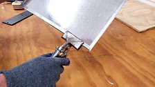
1. The student must cut the metal to 18" by 18", notch the corners in 1/2" and fold each side over with a metal folding tool. The hem can then be flattened down with hand brakes or a sheet metal brake.


2. On the sheet of metal, measure 1" in on all corners, center the sheet metal on top of the plywood and screw the sheet metal down with 1/4" zip screws. This sheet metal serves as the electrical ground frame.


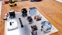
3. Mount all electrical components to the sheet metal board per the layout measurement sheet.

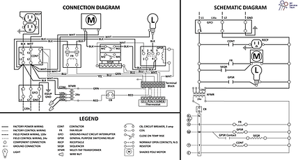
4. Review the Connection Diagram, Schematic Diagram and the Legend. The Legend shows the abbreviation and symbol meanings. The Schematic Diagram is a ladder type diagram that shows how the system works. The Connection Diagram shows how the system is wired.

5. Utilize the Legend and Connection Diagram to install the wiring. (The teacher gives step by step instructions to perform the crimping and wire connections.
6. Start installing the thermostat wiring from the thermostat to the terminal block.

7. Connect the 24v side of the transformer to the terminal block with the red wire being broke by the 3amp LI'L Popper circuit breaker.
8. Connect the 120v primary side of the transformer to the contactor inlet terminals. Individually wire nut each of the primary wires not used so they don't short against the ground.
9. Connect the GFCI wires to the contactor. Remember that the black hot wire should be on the NO switching side of the contactor. Connect the GFCI ground to the sheet metal ground frame.
10. Connect the G green wire from the terminal block to one side of the fan relay coil. Connect the Y yellow wire from the terminal block to one side of the contactor coil. Connect the C blue wire from the common terminal of the terminal block to the remaining side of both the contactor and fan relay coils as well as to the sheet metal ground frame.
11. Install the duplex receptacle using 14 gauge NMB wire. The ground wire is attached from the receptacle to the ground screw within the box. The hot and common wires from the receptacle get attached to the outlet side of the contactor at the lugs.
12. Connect the hot wire from the inlet of the contactor to the #2 contact on the fan relay. Connect the hot wire from #4 on the fan relay to one of the two terminals on the shaded pole fan motor. Connect the common wire from the other spade terminal on the fan motor to the common terminal at the inlet of the contactor
13. The student may now turn the power on to test both the fan and air conditioning positions on the thermostat. When pushing the FAN button to the right to the on position, the fan should immediately turn on. Push this back to AUTO. Push mode button to the right to COOL and turn the desired temp down to a lower setting than within the building. The thermostat has a 5 minute delay before sending power from Rc to both G and Y to turn on both the fan motor and the receptacle. If the light assembly is complete (ceiling box, NMB connector, light socket, 120v plug, light bulb), this and the 120v plug-in fan can be mounted to the receptacle in each plug socket.
14. At this point, the teacher may instruct the student to take measurements in order to understand what is happening. Removal of the thermostat face and jumping terminals with the Magjumpers can be done to reinforce thermostat wiring and the functions.
15. Turn the power off and disconnect the GFCI plug from the wall.
16. Connect one of the W white wires from the terminal block to one side of the GPSR coil and connect the other W white wire from the terminal block to the #1 contact on the GPSR.
17. Connect the C blue wire from the terminal block to one side of the sequencer pan heater and then connect this terminal at the sequencer to the remaining side of the coil on the GPSR.
18. Connect #3 NO contact on the GPSR to the remaining spade terminal at the pan heater of the sequencer.
19. Connect the hot wire from the inlet of the contactor to the #4 terminla of the GPSR and then connect from that terminal to one side of the top NO contacts of the sequencer. Connect the other NO contact on the top of the sequencer to the hot wire terminal of the shaded pole fan.
20. Connect #6 NO contact on the GPSR to the light socket on the board. Connect the common wire from the light socket to the common terminal on the inlet of the contactor.
21. The board may now be plugged in and tested for operation to determine if the heat light bulb operates and the sequencer turns on and off the fan with the proper timing mechanism. Turn power off to the board.

22. After the student has confidence in the project and awareness of how it operates, the student must thoroughly explain how each of the 120v loads are being powered. The student should point to and explain the 24v and 120v circuit paths.
23. Time for faults! The teacher should create faults within each project, 1 to 2 faults at a time. The student must find the fault by first noticing what is not operating and then measuring with the multimeter using strategies taught by the teacher. After determining the problem(s), they must report to the teacher to explain what they found and measurements. (It is very important that the student does not start pulling on connections to visually try to find the problem. Find the issues with the MULTIMETER!
24. The student will now be allowed to remove the bad connections and fix the board.
25. The teacher can now set more faults in it.
26. After the student gains mastery of the board and the troubleshooting of the board, allow the excelling students to add more components to the board such as the Delay-On-Make Timer breaking the Y wire to the contactor, or add a HSI next to a thermal limit switch, etc within the hearting circuit.
I hope this project builds confidence in each student's ability to problem solve! For those HVACR teachers out there, keep up the good work and continue to invest in young techs! I am always encouraged when I meet passionate teachers out there! You mean more than you will ever know and your diligence, attention to detail, and care means everything to students!
Speaking about passionate teachers out there, make sure to go check out Ty Branaman's youtube training videos!


